Overview
Twenty years ago, IRLabs was instrumental in delivering the IR camera used at Kagoshima University’s 1-meter infrared telescope. When lightning struck the observatory, we worked with the university to inspect and evaluate the damage to their camera system. The detector, temperature controller, filter wheel motor and motor controller were damaged beyond repair. Read-out electronics, electrical connectors, filter wheel coupler and other components were damaged or worn beyond specification.
Due to the age of the system, replacing the original Rockwell HAWAII-I detector was not possible because these products were discontinued and no longer available. Kagoshima requested proposals for a cost-effective way to rebuild the camera system using the undamaged optics, mechanical cooler, and vacuum enclosure since the high cost of new camera was outside their budget. IRLabs was uniquely positioned to take on this project because of our engineering experience, manufacturing capability, and a collaborative approach to solving difficult challenges.
Watch Video
Key Facts
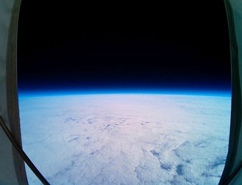
Project: 1-meter Optical Telescope at Iriki Station
Client: Kagoshima University
Project Location: Kagoshima, Japan
Application: Astronomy
IRLabs Product: Custom IR Camera System with Teledyne H1RG™ Detector

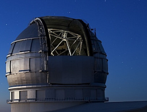
Kagoshima University’s observatory housing its 1-meter IR telescope.
Challenges
The main challenges were directly related to replacing the HAWAII-I detector with a new Teledyne H1RG detector and support electronics within the existing camera system. Challenges included:
- Different detector size
- Different detector layout
- New detector readout electronics
- New thermal mounting for cold internal readout electronics
- New application software for controlling the FPA and acquiring images
The camera optics in the original configuration illuminated one 512 X 512-pixel quadrant of the HAWAII-I array. The rebuilt camera will have a different detector layout that will illuminate the central 512 X 512-pixel region of a new 1024 X 1024-pixel Teledyne H1RG array. Although the camera will transfer the entire 1024 X 1024 image to the host computer, the application software can crop the image to the useful 512 X 512 region.
Other lightning-damaged or out-of-spec components will be replaced with these new components:
- Filter wheel motor and controller
- Lakeshore temperature controller
- External cables to interface with new temperature controller
- Camera vacuum window
- Filter wheel drive coupler
- Electrical case connectors
")
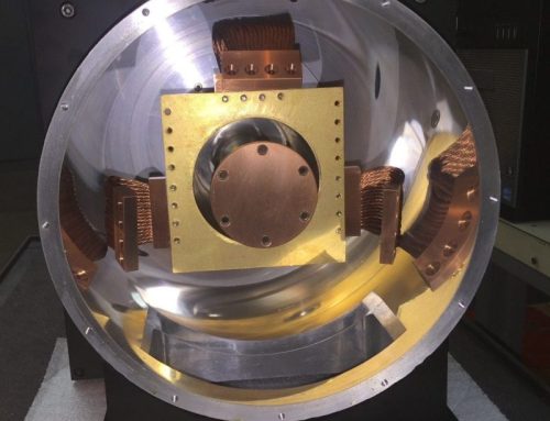
Original IR Camera System (circled) installed in 1-meter telescope.
Solution
This project started with a full inspection and evaluation of each system component. Considering our client’s need to replace the detector subsystem with new components while retaining as much of the existing camera as possible, we worked collaboratively to retrofit the system with a new array at a lower cost than purchasing an entirely new IR camera system.
We were uniquely qualified to retrofit the existing system in three areas:
- Knowledge of the original system and application
- Our successful track record designing and installing Teledyne detectors with AstroBlank Scientific detector electronics
- Expertise in application software for detector readouts
The new detector array will be mounted at the same focal location with no changes needed to focus and center the optics onto the array. After removing the destroyed Hawaii-I array, the mount, fan-out board, and cabling are being modified to accept the H1RG MCT array with a SIDECAR™ cryogenic application-specific integrated circuit (ASIC) and warm AstroBlank Scientific MACIE read-out electronics.
These components will replace the previous detector fan-out board and external preamp:
- New H1RG detector will internally connect to the cooled ASIC using a 4-inch ribbon cable.
- New ASIC electronics card will mount behind the existing cold plate, preventing thermal background noise from the ASIC reaching the detector.
- Room-temperature MACIE read-out electronics will be mounted outside the camera vacuum case and will be connected to the cold internal ASIC with a 15-inch ribbon cable
- The mounting location of the MACIE electronics will be similar to the mounting of the original preamp.
- Communication from the read-out electronics to the host computer will be either CameraLink or USB
We will supply a computer with the selected CameraLink or USB camera interface, Teledyne user software, and a configured copy of our own AIRIS software. Both software packages can control the camera and collect and process image data. The AIRIS software will be set up and ready to run out of the box to provide an easy and intuitive tool for collecting image data. The Teledyne software will be helpful for system development and integrating the detector control in Kagoshima’s astronomical imaging software.
In the tradition of our founder, Dr. Frank Low, the “the father of infrared astronomy”, we are proud to continue to advance IR astronomy in projects worldwide. While this project presented unique challenges due to the age and damage to the system, our retrofitted solution will enable Kagoshima to achieve its performance and budget requirements.

New detector chain block diagram.

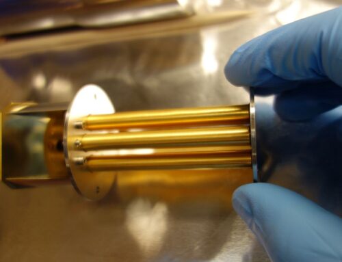
L: External view of camera with new MACIE electronics
R: Internal view of camera showing new detector chain